FP-1420-A-A81-SA is 1420nm pump laser modules uses a number of revolutionary design steps and the very latest material technologies to significantly improve scalability of the production process. The semi-cooled 45°C laser diode operation provides for a significant reduction in TEC and overall power consumption. The module meets the stringent requirements of the telecommunications industry including Telcordia GR-468-CORE.
The LD-PD Series pump module, which uses Fiber Bragg grating stabilization to lock the emission wavelength, provides a noise-free, narrowband spectrum even under changes in temperature, drive current, and optical feedback. Wavelength selection is available for applications requiring the highest performance in spectrum control with the highest power available.
Product model
Name
Model
Description
Parameter
Price
Parameter
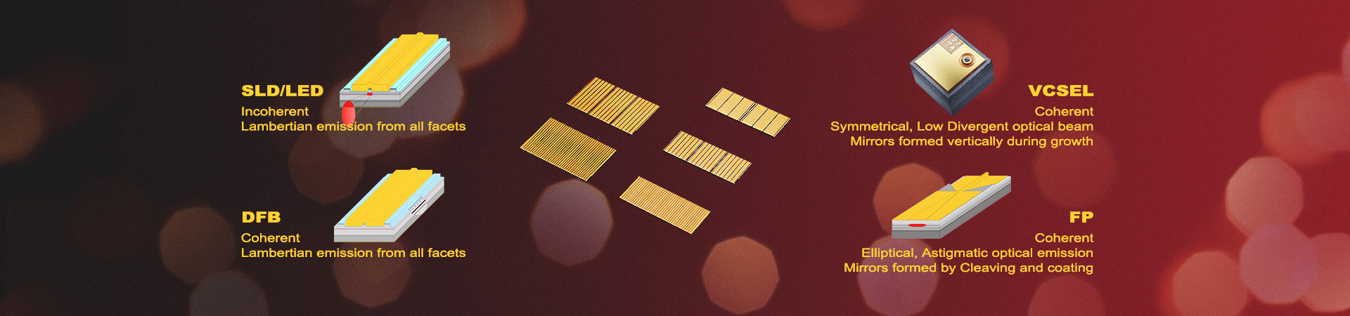
Features
● Optical output: Up to 650mW
● FC-APC connector
● 14-PIN butterfly package
● Wavelength selection available
● Integrated thermoelectric cooler, thermistor, and monitor diode
1. The tracking ratio is a measure of the front-to-back tracking when the output power is varied. On a plot of optical power versus back-face photocurrent, a straight line is drawn between the minimum power (30 mW) and the operating power (Pop) points. The tracking ratio is defined as the ratio between measured optical power (shown as data points on the plot) to the value derived from the straight line.
2. The tracking error is defined as the normalized change of output power relative to Pf at 25°C, that is, (Pf – Pf_25)/Pf_25, over case temperature range of 0 to 75°C, at constant back face monitor current corresponding to the lowest back face monitor current at Pf= Pop of 0°C, 25°C, 75°C.
3. Datasheet for Calculating Temperature from the resistance of the Thermistor is available now. You can contact us for details.
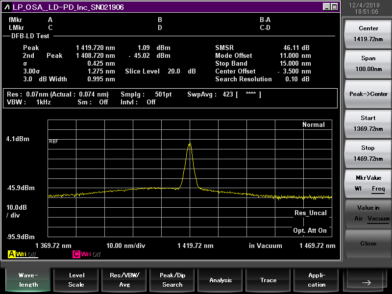
Spectrum
L-I Curve
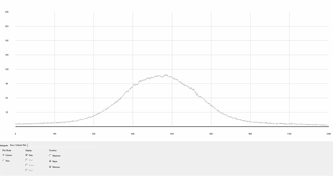
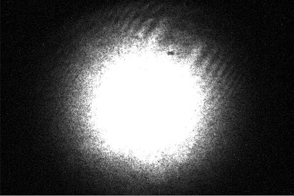
Digital Camera Analysis
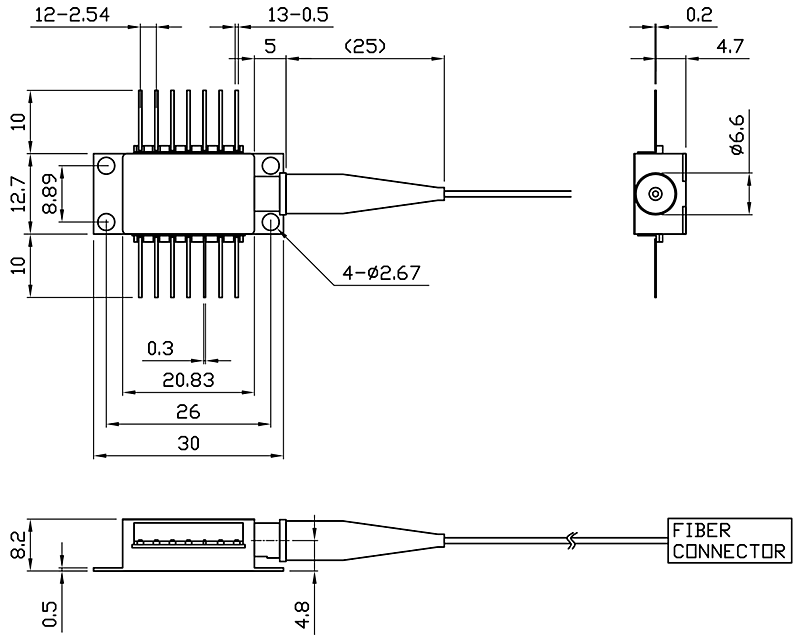
Package Size
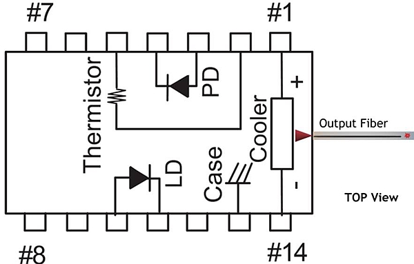
Pin definition
1
Thermoelectric Cooler (+)
8
N/C
2
Thermistor
9
N/C
3
PD Monitor Anode (-)
10
laser Anode (+)
4
PD Monitor Cathode (+)
11
Laser Cathode (–)
5
Thermistor
12
N/C
6
N/C
13
Case Ground
7
N/C
14
Thermoelectric Cooler (–)
SMF-28E Fiber Nominal Characteristics and Tolerances
Parameters
Specification
Cut off wavelength
1300nm
Max Attenuation
2.1dB/km
Cladding Diameter
125um
Coating Diameter
250um
Core Cladding Concentricity
≤0.5um
Mode Field diameter
9.5um
Absolute Maximum Ratings
Item
Symbol
Unit
Min
Typ
Max
Testing Condition
Case Temperature
TOP
℃
-5
25
70
Chip Temperature
TLD
℃
+10
25
50
Operating Current
If-max
mA
0
850
1500
Forward Voltage
VR
V
0.8
1.2
1.8
TEC Current
I TEC
A
-
1.2
2.0
Tec Voltage
VTEC
Axial Pull Force
N
-
-
5N
3x10s
Side Pull Force
N
-
-
2.5N
3x10s
Fiber Bend Radius
16mm
-
Reverse Voltage(LD)
V
-
-
1.8
C=100pF,R=1.5KΩ,HBM
Reverse Voltage(PD)
VPD
V
-
-
10
C=100pF,R=1.5KΩ,HBM
LD electrostatic Discharge
VESD-LD
V
-
1000
PD electrostatic Discharge
VESD-PD
V
-
500
PD Forward Current
IPF
mA
-
10
Lead Soldering time
S
-
10s
300℃
Store Temperature
TSTG
℃
-40
-
+85
2000hr
Operating Temperature
TOP
℃
-
Relative Humidity
RH
5%
-
95%
Noncondensing
Absolute maximum ratings are the maximum stresses that may be applied to the module for short periods of time without causing damage and are listed in Table 5.Stresses in excess of the absolute maximum ratings can cause permanent damage to the device. Exposure to absolute maximum ratings for extended periods of time or exposure to more than one absolute maximum rating simultaneously may adversely affect device reliability. Specifications may not necessarily be met under these conditions.
Application
● Pump Laser
● Dense wavelength division multiplexing (DWDM)
● EDFAs for small package designs
● High bit-rate, high channel-count EDFAs
● CATV distribution
Ordering Info
PL-FP-□□□□-☆-A8▽-XX-FBG
□□□□: Wavelength
1420: 1420nm
*****
1480: 1480nm
☆: Output Power
A: 300mW
B: 400mW
C: 500mW
D: 600mw
▽: Wavelength Tolerance
1: ±1nm
2: ±2nm
XX: Fiber and Connector Type
SA=SMF-28E+ FC/APC
SP=SMF-28E+ FC/PC
PP=PM Fiber+ FC/PC
PA=PM Fiber+ FC/APC
Labeling
Laser Safety
The LD-PD pump laser module emits hazardous invisible laser radiation.The pump laser module emits hazardous invisible laser radiation.Due to the small size of the pump module, the box packaging is labeled with the laser radiation hazard symbol and safety warning labels shown below
User Safety
Safety and Operating Considerations
The laser light emitted from this laser diode is invisible and may be harmful to the human eye. Avoid looking directly into the fiber when the device is in operation.
CAUTION: THE USE OF OPTICAL INSTRUMENTS WITH THIS PRODUCT INCREASES EYE HAZARD.
Operating the laser diode outside of its maximum ratings may cause device failure or a safety hazard. Power supplies used with this component cannot exceed maximum peak optical power.
CW laser diodes may be damaged by excessive drive current or switching transients. When using power supplies, the laser diode should be connected with the main power on and the output voltage at zero. The current should be increased slowly while monitoring the laser diode output power and the drive current. Careful attention to heatsinking and proper mounting of this device is required to ensure specified performance over its operating life. To maximize thermal transfer to the heatsink, the heatsink mounting surface must be flat to within .001inch and the mounting screws must be torqued down to 1.5 in/lb.
ESD PROTECTION—Electrostatic discharge (ESD) is the primary cause of unexpected laser diode failure. Take extreme precaution to prevent ESD. Use wrist straps, grounded work surfaces, and rigorous antistatic techniques when handling laser diodes.
By using this website and services, you agree to our use of cookies.
Cookies enable us to better provide member services and record your browsing records in a short time.
OKLearn more