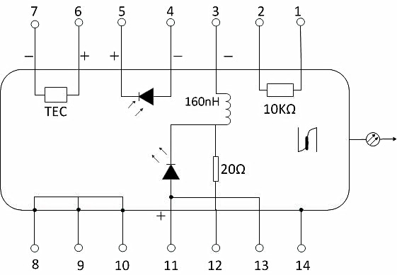
Features
● Compact all-in-one laser diode controller
● CW operation and external modulation up to 500kHz
● Operating current range 15 to 2000mA
● USB port and control software included
● Graphical User Interface for real-time monitoring, control and data logging
● 14-pin butterfly mount or 14-pin DIL mount included
● Additional mounts are optional
● Compact size (164x105x95mm)
● 110-240V AC adapter included
Physical/Optical Characteristics
Items | Parameters |
Compatible Laser type | 14pin Butterfly package/DILPacakge |
Power supply | 8~12VDC |
Driving Current | Max 2A |
Laser diode Driving Current |
Max Driving Current | 0~500mA/0-2000mA(Optional) |
Max Output Voltage | 5V |
Internal STW scanning period | 10~200ms (Set by Software GUI ) |
Internal STW scanning Current period | 0~200mA (Set by Software GUI ) |
External modulated signal’s Frequency Range(-3dB) | DC~100kHz |
External modulation coefficient | 200 mA/V ± 2% |
External modulated signal’s Input Voltage Range * | 0~850mV DC |
External modulated signal’s Input interface | BNC, Female |
External modulated signal’s Input impedance | 20kΩ |
Temperature Control |
Temperature Control Range | 15~50℃ |
Temperature Display Resolution | 0.1℃ |
Short-term stability(1hr airtight cavity) | 0.001℃ |
Long-term stability(1day airtight cavity) | 0.002℃ |
Temperature sensor | Resistance type NTC,10 kΩ±1%@ 25℃ |
TEC Peak Current | ±1A |
TEC Peak Voltage | 5V |
Temperature Control Interface | DB9,Male |
Others |
Computer Interface | USB type B |
Operation Temperature | 0~50℃ |
Store Temperature | -10~80℃ |
Dimension(LxWxH) | 22.8cm*22.0cm*10.1cm |
Weight | 700g |
Note:* The modulation signal peak level is determined by the max driving current of the laser diode,It may Permanent damaged the LASER DIODE When Customer over Modulated.Before Appling the Modulated Voltage into this Drvider.Please make sure the peak Voltage level of the driver suites for the LD’s Safe driving Current.
The following we give out two Operation Conditions
1. The laser modulation signal is only the external modulation input signal, External modulated signal’s Input Voltage is limited by the max Driving Current( ILim),The max peak voltage level Vmax should less than 5×ILim(A),and the lowest voltage should>0V, one negative voltage is prohibited.
eg:One DFB LASER DIODE’s max driving Current is 0.15A, External modulated signal’s peak Voltage level should be: Vmax≤5×0.15=0.75V,The lowest modulated peak voltage should be:Vmin≥0V;
2.When the laser modulated signal is selected as the synthesis with external signal and internal sawtooth.When the maximum current of the internal sawtooth wave is set at Imax, the minimum current is set at Imin, the maximum Volatge level Vmax of the external modulation signal should be less than 5 x (ILim-Imax) (A), and the minimum level Vmin of the external modulated signal should be greater than - (Imin /5).
Example: the maximum safe drive current of the laser, 0.15A,
The maximum current of the internal sawtooth wave is Imax=0.075A,
The minimum current Imin=0.015A,
The external modulation signal peak level Vmax is less than 5 x (0.15-0.075) =0.375V.
The minimum level Vmin is (0.015)÷(5) =-0.003V;
Software GUI

Ordering Info
PL-LDM☆-□
☆:
500:Max Driving Current at 500mA
2000:Max Driving Current at 2000mA
□:
A-Type A pin definition
B-Type B pin definition
C-Type 14 pin DIL Pacakge


